Tuesday 28 January 2014

Fairing Keel, fitting Centre Board & Sanding Hull

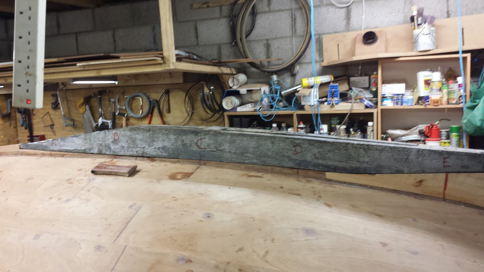
It's been 10 days since I last posted and I have been working most days since......and it's difficult to see the progress.  Sanding and fairing is a slow process.  I had no major issues to fair, other than the tail of the lead keel was veering to starboard slightly, so I made a plastic shuttering and filled with wood flour thickened epoxy.
That left a remarkably glass like finish.

I took several passes of creating a smooth radius fillet between the hull and keel with fairing epoxy, using a variety of sized tubes to create the radius and the sanding with the same tubes covered in 180 and 240 grit paper.  Eventually  I got a passable result.

Next  I went about installing the centreboard.  I measured carefully from the plans where to drill the pivot pins hole in the lead.  I clamped the trunk cap onto the trunk with a 30mm piece of timber in the slot so that the CB would rest in the truck at the planned level, when it is fully hoisted.
I took lines form the existing hole in the CB and extended them to the bottom of the CB where I could see them in order to line up with where I needed to drill the lead.

Armed with my trusty auger bit and brace, Siobhan helped my sight up the bit so that I drilled a reasonably straight and level hole across the lead.  When I first fitted the CB, it was inclined to sit proud from the lead, at a point 20" from the pivot point, where is was sufficiently recessed.
So I had drilled the hole at the correct depth, but for some reason which I haven't quite figured, the knuckle on the CB was hitting the inside of the keel preventing it coming up (or down depending on your perspective).  I had to relieve some 1/2" from the knuckle of the CB which then allowed it sit home safely contained below the bottom of the lead.

A delivery arrived from Classic Marine UK today which contained my standing and running rigging gear.  I'm really looking forward to fitting all these goodies!  But first I need to push ahead with painting the hull.  I spent most of Saturday vacuuming around the shop and yesterday Brian and I did a final sanding then hung light polythene as a tent over the boat.

So tonight, I took the plunge and having tacked the entire hull, put on a thinned coat of underwater Hempel primer.  It's like a silver paint and dried fairly quickly,  I just painted the hull below the water line, as I have a separate primer for above the waterline.  I'm not sure whether I am over complicating the matter with two different primers on the exterior of the hull - if anyone has any suggestions please comment below.


Saturday 18 January 2014

Installing Keel

Once I had cleared my thinking about whether to fibreglass the garboards and whether to install keel on while the hull was turned upside down, the time for action had come!

I called John Brooks. the designer of the Somes Sound 121/2 who explained the pros and cons of fiberglassing the hull - his view was that epoxy alone was a poor option and that if I wanted to use epoxy on the hull, I should also fibreglass it.  But when I thought further of how much the garboards are protected from abrasion by the protrusion of the lead keel, it became obvious that this was a wasted effort.  So I decided (again!) to stay with the marine paint and reply upon the quality sapele marine ply for durability....phew!!!

Next decision was whether to install the keel before turning the hull rightside up.  I was keen to pursue this option for reasons of access to final fairing of the keel into the hull and also since I have so little space in my workshop.  John felt that armed with the right lifting tackle the hull should be well able to withstand the forces of turning.  I then emailed Dave in SFO who also build a beautiful SS12.5 and pioneered turning the hull with the lead keel on, and he thought that my approach would work fine. Serendipity played its part when my neighbour and firewood supplier John gave me three large strong ratchet straps which were surplus to his requirements.   So that settled that!


I cut countersink holes in the keel with a forstner bit which was a little undersized but I was pleasantly surprised how well a straight bit in my router widened out the hole and gave a clean flat base.


Armed with these insights, Brian and I got stuck into fitting the lead keel.  I had repositioned the hull onto 4 cross timber to spread the additional load on the hull.  Also I coated the insight of the slot in the lead keel with epoxy to ensure that the surface wouldn't wear on the centreboard.


Fitting the keel  was not as straightforward as I had thought, as I had some difficult getting the bronze 1/2" bar down fully.   I had drilled the keel and keelson with a 12mm auger bit and thought that the slightly snug fit would be to my advantage however,  I should have really welded the top nut (or epoxied it beforehand) because relying on double nutting to screw the rod down only allowed me to go so far. I had to cut a a slot in the top of the rod to screw it down the final inch with a large screwdriver.  Panic set it as we realized the task was taking longer than anticipated as we wondered if the epoxy would kick before we got all finally bolted down.  We needn't have worried, but it was a close thing!!


Got to finish up by saying thanks to Brian and all contributors (Dave, John et al) who advised me so well on the process.  It seems like a real milestone has been accomplished!


Thursday 16 January 2014

Hull fairing, DWL and machining lead....

Spent a few days fairing the hull and sanding,  I am using a a Hempel epoxy fairing compound, which takes a bit of practice to get get right.  Initially I think I was spreading it too thick, until I realized that it can be skimmed on very finely almost like a thin layer of paint with a stiff plastic spreader - leading to less sanding
and a smoother finish.  Having sheathed the rudder and centreboard I was left with lots of minor blemishes which the fairing compound rectified.  I practiced on the centreboard as this will never be seen again!

Also I sealed the edges of the ply stakes with neat epoxy.  Once again, my wife Siobhan was right! "Why don't you just use a big syringe to apply the neat epoxy to the edges?"  Well thinking I knew better, I brushed it on liberally and spent the next two days scraping and sanding off the excess....

Here's a picture of the hull with the laps sealed prior to sanding.


Next came to finding the DWL on the hull.  Of course all the meticulously DWL lines I had on virtually every part of the hull had long been consigned to the sanding dust heap...so with Brian's assistance we reworked the DWL by taking various measurements from the plans and then using Brian's fancy self leveling laser, we scribed the DWL on the hull.

This photo doesn't really depict the DWL very well, as my long serving Nikon D70 finally died, so I have been taking pics with my Samsung smart phone which struggles a bit in the dark.

However, we were able to get a laser line running from stem to transom and they matched up quite well with the marks we made from the plans.

Here's Brian with his self levelling laser


Next step was to clean up the lead keel.  I needed to countersink the holes to accept the bronze washers.  The 1/2" washers have a 32mm external diameter and my Forster bit collection had a 30mm and 35mm, but no 32mm.  So I cut the holes out to 30mm and used a router with a straight cutting bit to widen and clean out the holes, which worked surprisingly well.

I had some holes, hollows and dips in the keel which I filled with molten lead and faired with epoxy.  I have more work to do before it is ready to fix permanently onto the hull.

I have been getting some good advice from fellow glued lapstrake builders on the yahoo forum.  I have now decided to sheath the garboards with epoxy and glassfibre, I only wish I came to that conclusion sooner, having spent so much time fairing the garboards already...

Also looking for some detailed advise on how to use slings to turn the hull with the lead keel bolted, so feel free to comment if you can offer suggestions.

Today was a busy day for the couriers....my order from Rutlands Tools arrived. Pride of place was a set of Japanese pull saws and a Quansheng #4 smoothing plane, plus a box of 170 assorted bradpoint drills and various bits and pieces for jig making.  Then some parts arrived from Classic Marine UK - keel banding, bronze tow eye, bronze dome nuts for the inside of the chain plates and some latches for the lockers -  which is quite exciting.  I'll take some photos tomorrow and post them (done!).  I am in the process of ordering the rigging parts from Classic Marine who are really great people to deal with - very helpful even to first timers like myself.  I'll write this up when the parts arrive, but so far it looks like they will supply an authentic rig.


Saturday 4 January 2014

Rudder, Centreboard and Keel fitting

It's been a while since I last posted and really that's because I procrastinated too much about what steps to take next - paint inside the hull or turn it over.  Once I got my plan straight, we made decent progress:

The bronze hardware had arrived, thanks to Ballentines Boat Shop who were extremely helpful and knowledgeable and Brian who collected the parts for me while visiting relatives nearby, so I made some progress towards completing the rudder.


Here you can see the gudgeons being fitted to the leading edge of the rudder.  Once I had these installed, I removed then and sheathed the rudder with fiberglass woven cloth.  This resulted in a reasonable finish but I reckon I will need to finish with fairing fillers to get a smooth finish.  I decided to sand off the glass where it curved around the trailing edge as it seems to stand somewhat proud from the boards edge, so I will also finish this with fillers.

Next I made some further refinements to the centreboard.  I followed a useful instructions sheet
published by the Gougeon Brothers which recommended drilling out the hole oversize , with wide chamfers at both sides of the board, for the bushing and remaking with glass cloth soaked in resin and finally assembled with a large bolt and two washers to squeeze the resin impregnated cloth into a smooth bushing.

The result was quite encouraging and I hope will last well.  Here's the finished result shown here with the bronze rod inserted.

So bolstered on with this progress, I assessed that the next thing I needed to do was turn the hull.

I wanted to drill the hull for the lead keel bolts, but the floors beams would have been in the way, so I concluded turning the hull was the only way forward.  Also I needed to seal the edge of the ply planks with epoxy resin and do some final fairing of the hull - best accomplished with the hull upside down.

Before I could turn the hull, I needed to the chain plates to the hull, as this process requires drilling holes in the hull.   Making the blocking board to fit between the hulls strakes and the bronze chain plates was quite slow and tedious, necessitating several attempts before I got clean fits.  I wanted a tight fit rather than relying on epoxy to fill the gaps, so that I could varnish them to show off the bronze chainplates.  My friend Brian came along to help, which was just as well as it was quite a brain teaser trying to figure out how much and which way to tilt the band saw.

Here on the right,  you can see the chain plate installed where it protrudes through the side deck beams.  Although it looks a little long here, there is an other Sapele deck to go on top.   I didn't cut the hole for the shroud as I have not taken supply of the rigging fittings and not yet sure what size to drill the holes.

Inside the hull, you can see where the chain plate is fitted to the backing plates.


Once the chain plates were installed, it was time to turn the hull.  Last time I did this with my friend Brendan and we managed quite well (at least Brendan didn't complain too much when I had him holding most of the weight and being squashed against the wall to protect the hull...thanks Bren!), but since then quite a bit more has been attached to the hull.  We set up two slings out of the ceiling, plus this time we had the benefit of the steel RSJ which we had fitted along with a sliding carrier for a block and tackle, not to mention two extra pairs of hands, thanks to Brian and Bren's son Scott.

However we slung the hull too high, so when it came to turning it over we couldn't get it to clear the ceiling (only 8ft - compared to beam of 6ft) so we had to reset it into lower slings and with much huffing and grunting we got her turned!  It's really a challenge working in such confined spaces - we had to practically rearrange the workshop to perform this simple task.


Once we had the hull turned over, we set to dry fitting the lead keel.  This is where the block and tackle running along the RSJ made for a smooth process.


The keel sat very well onto the  hull with only very small gaps - so the time and effort I put several months ago into fine tuning the keel's shape by using copious templates really has paid off.

I was quite looking forward to the challenge of drilling for the keel bolts - yet everywhere I read, the perceived wisdom seems to be to drill from inside the hull into the lead - which makes a lot of sense, because if the holes come out of the lead a little off line, it would never be seen.  However since this wasn't an option for us, we make a drilling template block taking the drilling angle off the plans and converting this on the pillar drill into the drilling guide.
 This was simple a length of 4x4 stock equal to the width of the base of the lead keel, into which we drilled to holes at 4 deg angle off vertical to allow for the bolts to exit inside the hull at the preordained positions.  We checked our template block first by inserting 10" long 1/2" dowels into the drilled alignment holes and measuring the distance from each end to see that it corresponding gap on the plans.

Next to the actual drilling process.  I had read so much about how drills break in lead and go off line, so I decided to use a simple brace and wood auger bit, which was quite hard work but very effective and we ended up with very satisfactory holes exiting either side of the centre board trunk inside the hull.  Here you can see Brian hard at work.  I read that acetone makes for a good lubricant for drilling lead, but I compared this to cutting fluid and found the latter to be much more effective.  Once we made through the lead, I switched to a hand held electric drill to go through the wood, which speeded up the process.  Since by 3/8" auger bit wasn't long enough to go through both the lead and deadwood at the same time, I finished off the deadwood when we removed the keel, having made a deep guide hole to ensure we were perfectly aligned.


Once these holes were completed we fitted the bronze threaded bar, which was predominately 1/2".  We had used 12mm auger drills , but the 1/2" bar was quite easy to thread into the slightly smaller 12mm holes which will hopefully make for good water tight seals.

Since we had such a hard time turning the hull, I didn't even contemplate leaving the lead on before turning the hull right side up again, even though I saw how Dave Johnson in his blog did so quite successfully.  So I faired in the forward part of the keelson into the lead and also the deadwood at the transom.  I will leave the final finishing when the keel is bolted on permanently and the hull is right side up.

Lead keel safely back on the trolley