Sunday 27 October 2013

Somes Sound - Midpoint of build?

Been busy lately on the internal fit out and getting to the stage where my boat is beginning to take shape. Some days I seem to make great progress, others you spend hours seemingly getting nowhere.

What does seem surprising is the amount of wood I still have left over - yet there doesn't seem to be that much more construction to be done.   Initially, I spent a good deal of time calculating the timber requirements, as I had to import it from the UK and didn't want to rack up unnecessary shipping fees by buying all at once.  I have lots of Sapele mahogany left over  - so maybe anther boat is on the horizon!

My next major step is to remove the decks which are dry fitted and seal the planking with epoxy, then turn the hull and finish the outside of the hull.  I'm thinking I will put on the primer coats and perhaps one top coat.  Also considering fitting the lead keel: drilling for the bolts and doing the final fairing, then removing it before right siding the hull again.

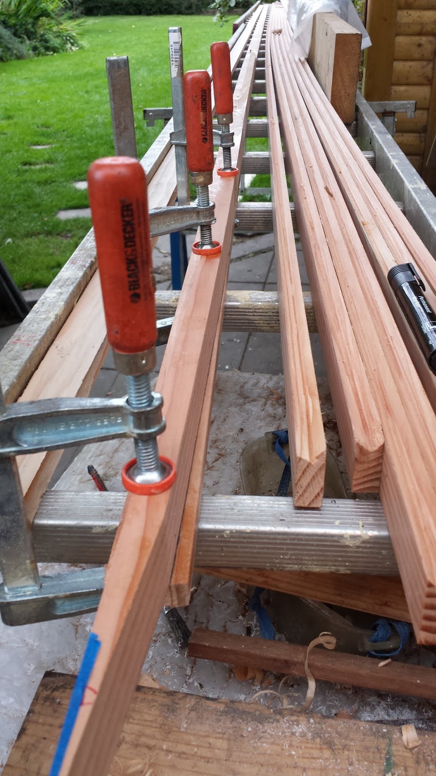
 I resawed a 45mm x 208mm Sapele board for the side decking.  Although the side deck is only about 2 1/2" wide, the curve on the hull demands quite a wide piece of stock to fit the curve.  By the time I resawed the 45mm board and planed it through the thicknesser, I ended up with only 3 slices of 12mm thick Sapele - plenty for what I needed, but nonetheless, 9mm lost in machining!  I debated on using some of the Sapele ply as it is such a good quality ply, but the rotary saw pattern isn't quite so authentic at the real board.

I experimented with some different bandsaw blades - trying a 1" blade which came with the saw (secondhand, but new spare blades)  The 1" blade was complete rubbish - smoke and squealing, so I switched for a new 1/2" blade I bought last year and the difference was night and day...


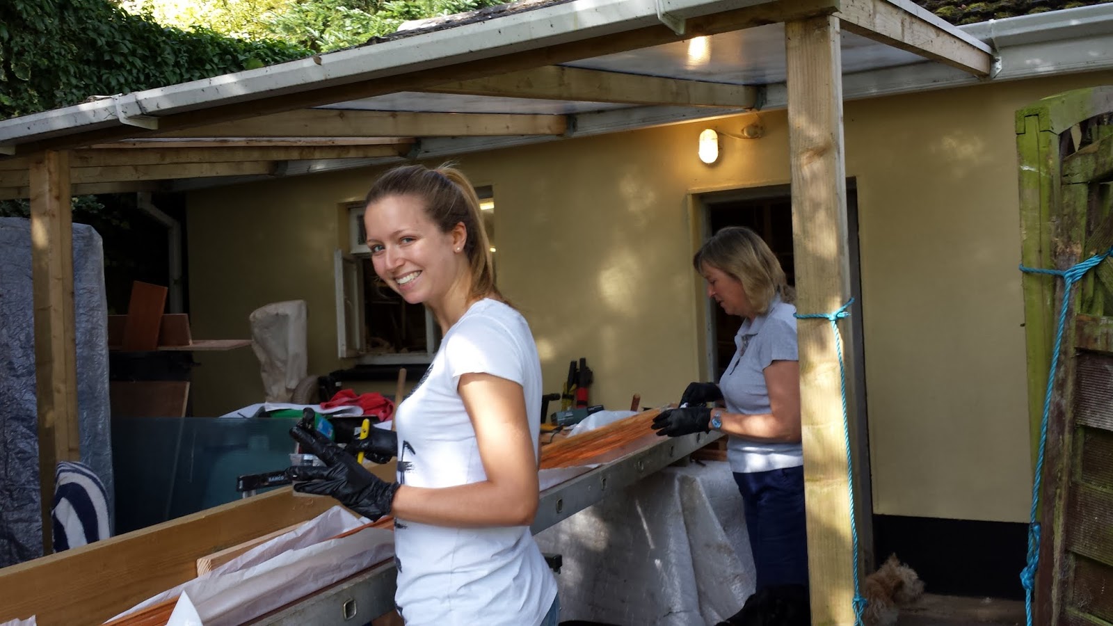
I also managed to rope in my friend Brendan to do another lead
smelt.  We fired up our old lead smelter, and poured about 20lbs of lead into the centreboard.  It went reasonably smoothly with no drama and the off cuts and left over scrap I had from the original keel or and now consolidated into nice shiny ingots...Thanks Bren!

I have to figure out the best way to carry the 16mm bronze rod which is used as a pivot pin for the centreboard.  I'm wondering if a piece of copper tube will suffice.


I have yet to make up Sapele trim for the lockers and shape up the hull rails, but I do think I have reached the  halfway stage of the build.

I am in the process of placing an order with Ballentine Boats in Cataumet, MA.  They are great people to deal with - very helpful and responsive.  Bronze hardware is very expensive so it's good to deal with people who are so genuinely helpful.  Thanks Tyler!

Here's a picture of the parts which should be coming my way soon:


Friday 18 October 2013

Front deck and side lockers

Making some progress on the decks and side lockers.  Using John
Brooks advice in specifications, I used a sheet of fabric to measure out the deck.  I managed - just to get both sides of of one 8 x 4 sheet of 3/8" ply.  In doing so, I had to shorten the side deck panel by about 1", which will simply mean that the Sapele solid deck will need to come forward by an extra 1" - no issue there.

While I used the manufacturers straight edge, when I cam to laying the two sides on the deck, for some reason which I haven't been able to establish, they did not site together seamlessly, so I had to plane a little off to get a better fit.  I don't imagine it will be a problem, as the deck will be covered in Dynel and epoxy, so a gap of 1 mm should get filled up quite easily.
I dry fitted the deck with 8 by 1" bronze screws.  I must have used 50 or 60 screws in the process - 2 of which broke in the deck beams, despite setting the torque on th electrc screw driver at a low setting.

Here you can see the deck before it was screwed to the beams and the edges cleaned off with a flush trim router cutter.

Next I moved onto shaping and fitting the side lockers.  John Brooks provides a full sized pattern in his plans for one of the locker sides.  So I made a template from this and used this to spile an exact copy for all four sides of the lockers.  However, this caused some head scratching, as the locker sides are fitted at stations 8 & 10 and these have slightly different hull profiles.  This resulted in the locker sides running out of alignment, so I had to do quite a bit of refining.  The next picture shows how the aft locker side is higher than the front, which would have cased the seat to run off level, unless lines to the aft bulkhead were checked.  Sounds obvious, but anytime I have deviated from John's plans I have subsequently found this to be at my cost...hopefully I have it right this time.  Once again a quick email response from John satisfied my doubts.

Next I started to create the V notches in the side locker panel.  Based on a suggestion over on the BuildingGlued LapStrake Yahoo groups of using a jig on the router base, I made a simple base with a plastic strip guide.  This worked quite well, though with some refinement could be better...ideally longer.

 Here you can see the base of the jig attached to a small router and the
resulting grooves cut into the side panel.


Monday 7 October 2013

Internal Fit Out - continued...

My next step was to build the aft bulkhead and install the aft deck beams.
The plans call for 3/8" ply (I'm using Robins Elite Sapele) which can be fitted either as one component or two halves.  I elected to fit as a single component and so had to first scribe a vertical line on the inside of the hull where the bulkhead was to be positioned.
I spent considerable time with a laser beam with limited success so I ended up using straight edges clamped to a spirit level amidships, having first checked and rechecked that the hull was sitting level fore & aft and bow to stern.

Using a joggle stick which I clamped vertical on the hull, I drew point on the spiling board at each plank land which I then transferred onto the plywood to cut out the bulkhead shape.  This proved quite successful although I needed two different joggle sticks to account for the longer lengths.

Having cut out a template and satisfied myself to the final measurements, I transferred the measurements onto the final stock.

 I then routed lines into the panel to imitate the paneling effect.  I used a simple jig to space out the lines but on one run managed to misaligned the jig so I ended up having to fill the errant line with epoxy---shouldn't matter as this panel is to be painted.

I also brushed neat epoxy into the routed cuts to seal the ply.  It fitted well into the hull requiring only small fillets of epoxy to make for a sturdy joint.

So far so good.

Next stage was to make the doors and fittings for the bulkhead which John Brooks advises to do before fitting the bulkhead.  The plans call for the fitting to be looser than what you would allow for normal cabinet building...Hah - not ever having built a cabinet before, I reckoned that making them looser would most likely be the outcome!

The profile of the trim called for quite a complex Z shape, which was to be repeated for the side lockers, so I elected to make all three at once.

Here you can see the Sapele being shaped mainly on the table saw and then router.  I was quite pleased with the result.  Next came to jointing the pieces which was quite time consuming but enjoyable work.  The lower edge required a different profile with a small angled sill.

I decided to use TiteBond 3 to glue up the joints as they seemed to fit quite snugly and are not structural...plus I want to varnish these pieces so the TiteBond glue line should be less visible than epoxy.

Next step was to make the doors which also are encased in a Sapele frame, using half lap joints,  This worked out quite nicely and I think it looks the part.  When I first saw the Somes Sound in John's workshop, I was unsure if I could make such intricate (at least to my eyes) components, so I derived great satisfaction in getting them made.

Once I had all three frames and doors made, I installed the rear bulkhead.  This time I used tape to form a neat fillet of epoxy.  I'm not sure I would do this again, as the tape was quite difficult to remove later when the epoxy had set.  Perhaps I should have pulled the tape once I was finished laying the epoxy and before it hardened.


Once the aft bulkhead was installed, this gave me the reference height to fix the transom cleats for the aft deck.  I was unsure as to how these cleats should be fitted, and a quick email to John Brooks elicited a very swift and concise response (Thanks John!) where he described how to make and use a declination level, whereby the level is fixed to a batton and raised at one end to allow for the correct fall from the aft end of the deck towards the bulkhead, so ensuring that water is not left lying on the deck.  Also the deck has a camber to the sides to promote a dry deck and fair lines.

 The camber of the bulkhead is repeated in the deck beams and also the transom cleat.  I made a template of the camber which ensured that all decking components were identical.

Additionally there are two curved cleats attached to the hull between the bulkhead and the transom.
 Initially I misread the plans and so made them such that they lay to the same level as the top of the transom cleats on one end and to the top of the bulkhead at the other.  Then on closer inspection of the plans and building instructions, I realized that these side cleats need to be lower down so that when the deck is attached, there is a gap between the deck and the hull so that water can drain down each side and to a limber hole aft of the bulkhead.

This is a very thoughtful detail, as it ensures that any water draining off the deck is carried away unsighted behind the bulkhead and into the bilge through two further limber holes at the bottom of the bulkhead, leaving the exposed surfaces of the deck and bulkhead unblemished by water marks.  The more I get into building this boat, the more I am impressed with the attention to detail that John Brooks has engineered in his design.


Here you can see there the aft deck beams sit on top of the side cleats to ensure that the deck is fitted with a gap from the hull.

The plans call for quarter knees to be fitted to the hull and transom, but it is not clear to be how they should be designed - as the drawings do not look as if  conventional knees are fitted on a horizontal plane between the transom and the side deck filler, rather sitting on a vertical pace between the transom cleat and the hull.  I'll have to ruminate on these a bit more before deciding on how to proceed...unless any other SS builders out there can comment?

Next stage is to build the side lockers which provide support for the side seating.  I have already made the doors and frames and a template for the sides of the locker, so it shouldn't be too long before that's accomplished.  However we're heading off for a trip to Budapest to visit my daughter who is attending university there, so the building will have to wait until my return.

More later....Please feel free to comment with advise, critiques or suggestions.


Thursday 12 September 2013

Internal Fit Out

Having completed the mast, I have resumed work on fitting out the hull.  I deciphered the plans for the mast step and installed these components between the mast bulkhead and trunk. In order to shape the supports for the mast step,  I tried using a spiling stick (or jog stick?) which gave reasonable results, in two dimensions, but when creating a three dimensional part - the third dimension being to follow to curve of the hull from forward to aft - it has limitations.  I'll get a photo of it tomorrow to make it clearer!
Hastily constructed steam box!
Next onto installing the deck filler onto the sheer clamps.  I cut stock from DF and then cut a 15deg bevel off one side.  This however proved very thick to bend inside the sheer clamp, so I tried my hand at steaming.

Being new to steaming, I elected to use a 4" soil plastic soil pipe.  I found a plan on YouTube which showed simply plugging both ends and using wooden dowels along the bottom of the pipe so that the stock is not resting on the wall of the pipe but rather on a rack of dowels.

I had a Black & Decker wallpaper remover steamer device which I was able to plug into a brass adapter in one end of the pipe.  


It created
quite a strong supply of steam, however on the first plank I wasn't able to get the pipe much hotter than about 180F whereas I understand you need it to be around 200F to 210F.  The result was ok but I don't think I left the plank in long enough and so it was still quite stiff when I came to clamping it to the outside of the hull to take up the sheer clamp shape.  The next day when I took off the clamps, the stock retained a decent curve but had considerable spring-back nonetheless.  Next came the slow process of cutting the end of the deck filler to align with the transom and over the transom cheeks which made for a tricky join and at the other end a simpler join to the bulkhead.  I found it difficult to get a tight fit at the bulkhead.  My process was to butt the end of the piece to the bulk head and then slide the aft end down at the transom to line up alongside the sheer clamp.  Each time when I clamped up the deck filler to the sheer clamp, the for'd end of the deck filler would move back by 2-3mm from the bulkhead and the friction of the boards facing each other seemed to prevent it moving back in place, despite repeated thumps from ever increasing sized hammers!  In the end when it came to glue up, the epoxy acted as a lubricant and so the joints came up snug.
Next process was to fit the coaming knees.  This was made simple by the addition of full sized patterns in JB's plans.  Clamping the knee to the bulkhead proved nigh well impossible due to its shape, so I used bronze screws to secure it both to the sides and bulkhead.  

Next I have to refine the 15deg bevel along the deck filler to accommodate the coaming.  I made up a plywood former with the 15deg angle on one side and a small torpedo spirit level attached to the other, which will allow me ensue that the coaming angle is accurate.  Initial trial testing indicate that I have only minor adjustments to make, however I think that the coaming angle makes a very big visual impact on the look of teh boat so I will trial fit patterns before signing off on this process.

Friday 30 August 2013

Birdsmouth Past Mast - Day 6

Birdsmouth Mast - weighed a hefty 45lbs this morning - 7 hours later plus lots of elbow grease, it's now 34lbs!  That's 11lbs worth of shavings which were created by hand by your truly...

Today the planing was more successful, accompanied by several trips to the Japanese Waterstones. The plane worked effortlessly taking of shavings some of which were 3 foot long!  (Is this a record?!!)

The bulk of the work was getting the taper down to the required dimensions - once that was accomplished, rounding the octagonal shape to 16 sides and then round went very quickly.  Which serves as a useful lesson to other builders contemplating using a compound taper - it's a lot of extra work.

I did have some issues with different staves having its grain in opposite directions each side of the scarf joint, which meant I had to reverse the planing direction.  I found that the #6 Foreplane worked well when pulled, Japanese style, which allowed me use different muscles rather than just pushing all the time.

Using my spar calipers, I made sure that the diameter was uniform at each station.  Also, I kept the octagonal shape, which made for more consistent planing.  I was even tempted to leave the mast finished in octagonal form - I really like that shape...throwback to my early days with split cane fly fishing rods....

I decided not to reduce the diameter down to the final dimension at the top quarter of the mast, as I was nervous that the extra planing would remove too much of the birdsmouth joint.  However since the mast was coming out so relatively light, I didn't feel that this would be a handicap.
Bottom of mast showing internal plug made also birdsmouth style
I made sure to mark and keep the track (aft) side of the mast straight when gluing up and in the finish, I left this side straight to take the sail track.  It's probably too wide at 35mm, but I'll refine this when I get the track in hand.  I have no idea where to source this - can it be shipped in a coil or is it bought in one long length??

I recall reading on some forum where it was suggested to keep planing until you are finished or bored...I think i took the latter route, but nevertheless, I now have a nice 23' spar hanging diagonally from the ceiling of my 20' x 20' workshop. Phew!!

Thursday 29 August 2013

Birdsmouth Mast - Day 5

This morning I unwrapped the mast from its overnight coat and was pleased to see that the epoxy was well set.  So I enthusiastically set about planing back the mast  - first removing the epoxy coat from the wood was quite a struggle - even my trusty farriers file was baulking at the challenge.  I alternated between it an an old Anant Jack plane which did a reasonably job, still by lunchtime I had just about removed all traces of epoxy.

I raised the mast vertical to see how manageable it is - quite a handful, but then there is lots of material to be removed as I had only placed 50% of the taper in the staves width.  This sounded like a good idea at the time, courtesy of John O'Neill article, but the reality of planing back so much taper is quite a drudgery.

Out with the Foreplane and the additional heft was giving me some advantage, but only later in the day did I take time out to resharpen the blade, which made a considerable difference.Duh!!  However by that stage I was quite tired so resigned myself the the fact that my mast was going to take longer than 5 days!.

So far I have been planing back the taper while keeping the mast octagonal - which I think make for a more uniform approach.  I did take time out to research making a a spar gauge for 16 sides, and while it seemed to be a sturdy gauge, the pencils lead kept breaking and so in reality was not a success.  Maybe I can replace for two ballpoint pens and see how that
works out...maybe others have better ideas??  Please feel free to comment.
I transferred the dimensions at the various stations onto my workbench (ladder) and used a calipers to constantly check my taper.  This was quite depressing....several passes of the plane on eight sides just for 1 millimeter!  I need to take up to 5mm off the staves in some parts!  

I'm beginning to doubt the wisdom of only taking 50% of the taper from the width of the staves as the result is that the planing of the outside of the mast is leaving the shape of the birdsmouth joint asymmetrical and could even results at the very top of the mast where the birdmouth joint just becomes an edge joint, although that may not be a problem as there is a solid plug at that point.  I also had some excellent feedback from Dave Johnson who recently completed his Somes Sound and blog.  Dave also built a birdsmouth mast but did not increase its diameter from the specified width of the solid mast.  Dave reports that the boat sails really well and the mast is light.  You can see his excellent blog here and admire a beautifully build Somes Sound.

Wednesday 28 August 2013

Birdsmouth Mast Day 4


This morning, I cleaned off the epoxy from the inner plugs using my trusty farriers file....easy!

The plug for the bottom of the mast seemed a little oversized and I had to plane it quite a bit to get a good fit, especially at the base of the mast where it is tapered down from the gooseneck.  Brian made up the solid plug or the top of the mast - we planed down a 50mm square piece of DF stock - with hindsight, it might have been easier on the table saw, as the octagonal shape was hard to form freehand.

So today was somewhat of a milestone...we finally managed to get the mast glued up, which was a family/team effort with Siobhan, Jane & friend Brian gloved up and spreading epoxy over 8 staves on 3 sides, each 23' long...so 552 ft of stave surfaces covered, while Clare took the pics!  We used old toothbrushes which proved superior to small paint brushes which were improved somewhat by cutting their bristles short.

I set up the ladder straight such that the mast would lie flat on the rungs of the ladder and so define a straight edge which would be the aft side of the mast, transferring all of the taper to the front of the mast.  I'm led to believe that this will allow for better sail trim as well as a straight sail track.

We made up ply forms the with an octagonal hole in them which helped considerably in forming the mast together...just one at each end and the mast was quite easy to assemble.

Here you can see the mast epoxied and initially assembled.  We used a variety of hose clamps, cable ties and spanish windlasses to pull the staves together.  This produced a satisfying squeeze out, which reassured me that we had adequate epoxy in the joints.

Tomorrow I may start planing down the mast to its final dimensions.  We have deliberately left half of the taper to be removed from planing the outside of the mast rather than solely tapering the width of the staves.  However as I do not yet have the hardware to position on the mast, I will leave the mast rough finished before finishing to final dimensions, which should allow some wiggle room for fitting the hardware.  The specifications call for a rectangular shape to the head of the mast to facilitate mast fittings and a square base to sit into the mast "step" ( I think that is the right term).  Given that my mast is now octagonal, I will have to examine how best to make the step for the bottom of the mast.


Tuesday 27 August 2013

Birdsmouth - Day3

I read where someone created their birdsmouth mast in 5 or so hours...well this is Day 3 and still not finished, but steady progress nonetheless.

Rather than fiddling around with taper jigs for the tablesaw, I took advantage of the clement weather and fired up my Quansheng Foreplane and tapered the staves by hand.  In fact it was quite a fast operation and I felt a lot safer in the process, still smarting from yesterday's episode on the table saw....

Once again Brian came along to lend a hand...very welcome when managing 23ft staves..

The staves have all being tapered according to the dimensions which I worked out  (see earlier posts) and I made up two plugs in birdsmouth design for the bottom of the mast and where the shrouds and forestay are fastened to the mast.  I feathered the ends of the plugs to ensure no hard spots exist.  I'm hopeful that the extra effort will result in a sturdy light mast.

Tonight I glued up the birdsmouth plugs which was quite straightforward, although I was surprised at how much epoxy was used in the process.  Tomorrow, I plan to clean off the plugs and plane them down to size to fit the inside of the mast.  Hopefully by tomorrow evening I will have mast finally glued up, and then Day 5 will plane down and bring the mast diameter to its final dimensions.....so much for 5 hours!

Monday 26 August 2013

Birdsmouth Mast - Day 2

Today I managed to clean down the scarf joints armed with my Farriers File - Thanks Andrew for the hint!  The scarf joints turned out well and the staves dead straight, thanks to the aluminium ladder which I rigged up hastily as a bench.

The duck tape worked fine to hold the scarf joint together while the epoxy set over night.  Additionally I lightly clamped all the staves together separated by polythene sheets against the side of the ladder which further ensured that everything was held straight in both vertical and horizontal planes.

Then assisted by Brian, we ran the staves through the planer to clean up the saw marks and reduce the staves to their final thickness, 13.6mm.   Once again the ladder made for a very serviceable outfeed table.

Once we had the staves dimensioned we cut the lengths to the approximate size of 23' which allowed us remove several feet from the least attractive ends of the staves and also resulted in the scarf joints being positioned more randomly along the mast.

Next came the process of cutting the birdsmouth V notches in the sides of the staves.  We set up the table saw using two featherboards which resulted in a consistent clan notch cut from the staves, except for the last few inches where the stave ran past the feather board.  This shouldn't cause any issue as we have cut the staves extra long by some 7 inches.

The featherboards kept manners on the staves as they were passed through the table saw, however on the second pass of each stave the saw produced needle shard cutoffs one of which was expelled into my finger with some force, resulting in a badly swollen finger...So my advice would be to be watchful for this and wear gloves, which I subsequently did and benefited from their protection as further needles were projected from the saw.

So next on the agenda is to cut the taper into the staves on the side opposite to the V notch.  I have not yet decided whether to make up a jig for te table saw or simply place all the staves side by side and use an electric and hand plane to cut out the tapers.