Friday 28 March 2014

Progress on Coamings

John Brooks, SS designer, did warn that the coamings are the most difficult part pf the boat.  He's right! John has issued further detailed instructions on how to make the coamings.  The process is to first laminate the two halves to each other, but not glued to the boat.  Then remove, and lay and epoxy on the dynel cloth onto the deck.  Once set, the finished coamings are attached.

On my previous post you can see how I grafted some additional material to the end of one side of the board. The glue up on the plank turned out fine, although had I planed the board before glue up I might have been able to match up the pattern better.  As it happened while I grafted on a piece from the same end the board, it did cross over a very attractive grain pattern.  Nonetheless, the joint was clean and tight and I think it looks just fine.

I then ran the board through my thicknesser before resawing.  Although I needed 4 x 1/4" thick boards from the board which measured 2"+, it's still a challenge to resaw this accurately.  First I resawed into half  - which went reasonably well but even the smallest wavering of the bandsaw blade eats into your usable stock.  I then thicknessed again before final resawing into the 1/4" boards.  As it happened I ended up with slightly different board widths but the sum of the parts equaled the required 1/2".


The final thicknessing was done with both 1/4" boards held together so that I was able to accurately thickness down to the 1/2" dimension.  Lots of noise, dust and helping hands from my wife and daughter!
The following day, Brian and I attempted to bend the boards into place.  
It went reasonably well until crack! - one board developed a slight crack where it meets the deck.  JohnC who is also building a Somes Sound did warn me about this and suggested using a layer of glass cloth epoxied in between the laminates.  So we planed back the inside of the laminates for about 5" either side of the stress point and epoxied a light glass cloth into the planed area.  Once sanded it was completely flush with the rest of the board and made for a strong and flexible solution.

You can see in this next photo the board with the glass epoxied into it where it meets up with the foredeck - an obvious stress point.  This is just one laminate - the other half, which also has a glass cloth insert, will cover this entirely.

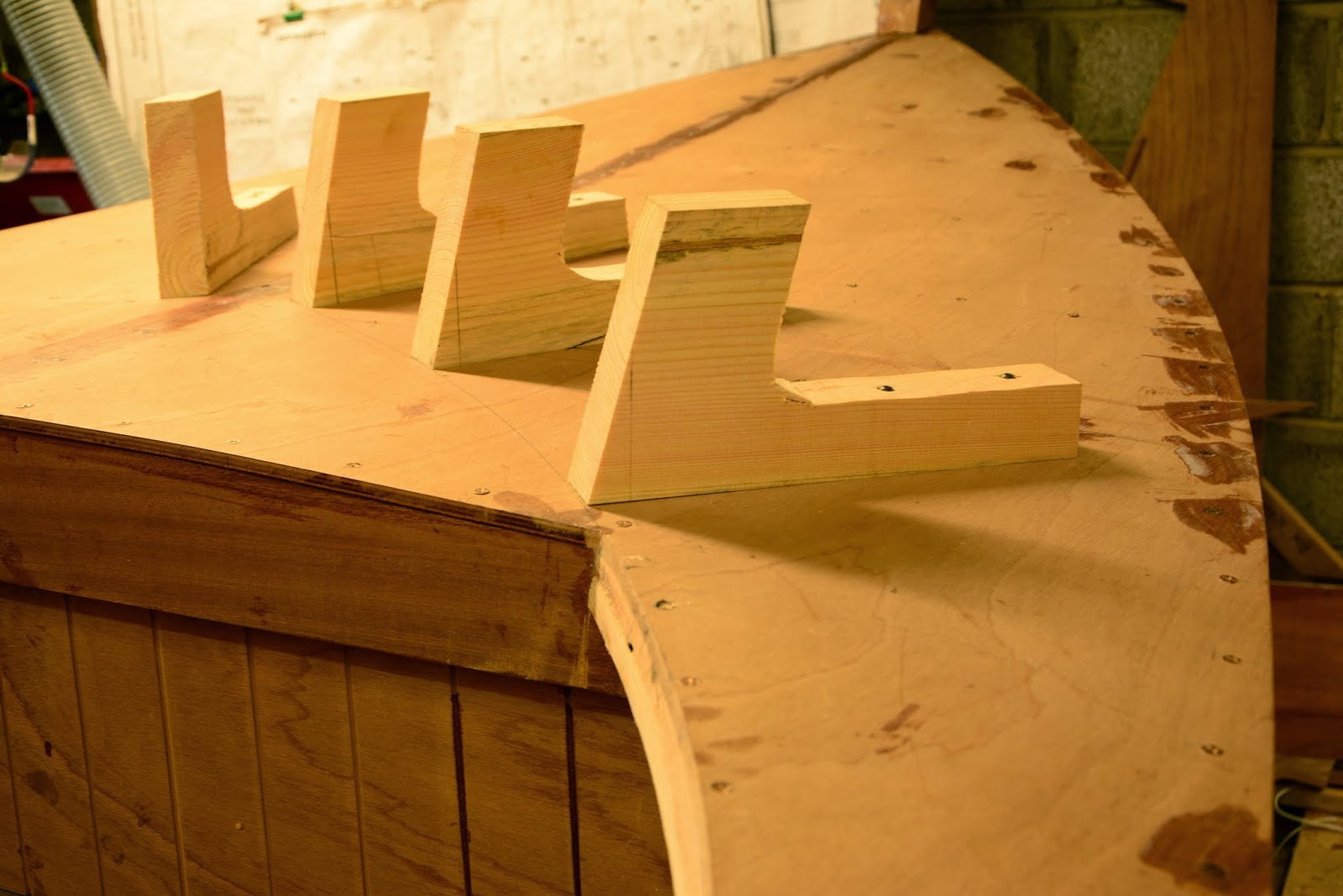
We had to make up several clamp extensions, as none of my F-Clamps reached more than 6" and the coaming needs clamping in areas wider than this.  They are crude but effective - just two lengths of timber separated by a block and wired together, over which a regular clamp is used to apply pressure through the clamp extension legs. We ct a 15deg bevel on one side of the leg, which ensures that the coaming was evenly clamped to the side deck filler.

Once we had one half reasonably fitting, we cut down the edges to size using a batten to create fair lines.  This reduced the width of the board making it easier to bend.  The epoxied glass cloth worked really well and no sign of crack appearing at the stressed areas.   We then cut out the second laminate from the first board, making sure to continue the bevels at the transoms and foredeck - the two halves are not identical.

The glue up went smoothly and the subsequent fitting was easier than when the boards were dry as the epoxy operates as a lubricant initially before it starts to kick.

Here you can see Brian admiring the motley collections of clamps!


Thursday 20 March 2014

Decks & Coamings

Now with the hull right side up, I needed to attach the decks permanently.  But first I needed to sort out inspection hatch for the front bulkhead and install the eye bolt in the stem.  I'd read somewhere that the eye bold should ideally be placed closed to the water line if used for towing,
whereas for pulling onto trailer, I guess a higher position would be more desirable.....compromise ensued and I positioned it just below the bronze plate for the forestay and above where the bronze keel band will end.

I had cut out the hole for the bulkhead inspection hatch, in a oval shape centered on the bulkhead.  Subsequently I had seen other builder use two hatches, either side of the mast.  However, since I don't intend using the flotation chamber for storage, I'm satisfied that the centered position behind the mast will work fine.  I'm working on the assumption that is is only needed for occasional airing of the chamber during off season.

Next was to epoxy and screw on the decks.  I also painted on a second coat of clear epoxy on the undersides of the decks before final assembly.  The camber on the fore deck was too severe for the 1" screws on their own, so some clamps were needed to pull the deck down tight and then the screws were able to keep it there.

Next step was to make up blocks to clamp on the coaming.  There is to my mind a peculiarity in the plans which state to bevel the side deck filler to 15deg and also make the clamping blocks to 15deg, but these block are sited on the foredeck which already has some camber on it, so this results in the coaming flaring out where it sits on top of the foredeck.  I'm not sure if this is by design, but I will wait until I trial fit the finished coamings to decide which has the fairest lines.

I made templates from 1/4" ply.  The plans call for 11 1/2" wide template, but it turrns out you need wider if you want the coaming to cover the side deck filler.  This necessitates a 14" wide board, which would leave quite an amount of waste cutoff.  So I decided to glue up a 10" board like so:

Using John Brooks excellent technique which he describes in his Glued Lapstrake Wooden Boats book of running a router bit between the joint off the one guide, I got a very tight joint, so I am hopeful the glueline will be invisible as I used the cutoff from the same end of the board.


Next job is to resaw this board into 4 1/4" boards.  The coaming can be either steam bent or made from a laminate of two 1/4" boards, so given that I will have a glue joint in the board, that rules out the steam option.

Onwards!


Saturday 8 March 2014

Hull Turning

I've had a few requests for further explanation on how I turned the hull, while the lead keel was attached.  I had some reservations about doing this - wondering if the hull itself was strong enough to carry the keel upside down - but an email to the designer, John Brooks elicited a swift reply to say that it would be fine.  I had seen where Dave Johnson in his building blog of the SS 12.5 also had taken this approach and Dave also confirmed to me that it was quite straightforward.   So, armed with these encouragements, I decided to take this approach.

To recap, I installed an I-beam spanning wall to wall running perpendicular to the hull.  This carries a rolling beam trolley
onto which I attached a relatively light 1-tonne block and tackle.  This allowed me to lift the lead keel onto the hull by simply letting the chain loop through the centreboard slot in the lead around a short length of flat steel underneath and attaching the eye to itself above the lead keel.  Once, I found the balancing point, the keel was docile and easy to manoeuvre.  I simply lifted it off a small trolley on the ground beside the hull and used the beam trolley to position in directly over the keel on the hull.
 This trolley proved very useful at various stages for manoeuvering the keel, and I am hopeful that I can use it also to wheel the finished boat out from the the garage.

Here you can see the keel being lifted onto the hull, with keel bolts ready, prior to epoxying the keel.  Before setting the keel onto the hull, I placed additional timbers from beam to beam to support the extra weight on the hull.  Once in place, extracting the flat steel plate from underneath the lead keel, I used a garden root cutter to pry the lead off the hull, while spreading the load across the cutting blade. A flat wide spade would probably work just as well.  You need to have some system figured out in order to remove the flat steel, as the weight of the lead will cause damage to the keel, if you try to pry the lead up with a narrow tool.

Next step having secured the keel and faired it into the deadwood, paint the hull etc., was to create a set of slings to support the hull while turning it over.  I used ratchet straps for the slings.


It's quite important to have the fixing points for the slings far enough apart so that when you turn the hull on its side, the narrower profile on its side doesn't allow the hull touch the ground. I have a small loft over the workshop, so I just drilled holes in the loft floor, positioned lengths of timber perpendicular to the joists over the loft floor to run the straps around and back through the holes.  When I first turned the hull around (before the lead was installed), we had quite a hard time, as we had made slings from ropes which were positioned over the hull approx 6ft apart (same size as the beam).  This proved troublesome as the hull dropped too low when on its side.  We were able to manhandle our way out of trouble, but that would not be an option when the lead is installed.  By comparison, I reckon the anchor points for the slings when we made our most successful turn was about 14ft apart, from an 8ft height.  (yes it's a small tight workspace!) On a different occasion we had the slings even wider apart and this also proved difficult as the hull was not inclined to swivel as easily.


Here you can see the hoist having been threaded through the centreboard slot.  To protect the top of the trunk we took a 4ft length of 2x6 stock and drilled a 30mm hole through it.  The chain loop was put through the hole and a length of steel bar placed through the chain loop which then was pulled tight against the 2x6, which in turn rested against the top of the trunk.  The hoist eye was too wide to pass down through the centreboard slot, that's why you can see it looped back onto the chain outside the lead keel.

My friends Brian and Brendan were on hand to help with the turnover - as it transpired they ended up having to complete it themselves, as I rushed off to a forgotten appointment!  No drama, apparently the hull rotated in its slings, while the trolley for the hoist was moved across the I-Beam and locked in place to one side with ViceGrips.  This allowed them to use the hoist to pull the hull around in its slings, and when it reached about 50deg they propped up the lead keel and released the hoist.  Then they reattached the hoist through the centreboard slot from the opposite side, with the following result.

So the secret to stress free hull turning is to bring your friends along, set up the operation and then make some flimsy excuse about having to go to an important appointment!  Come back 2 hours later to find the hull right side up and sitting it its slings!

I should say that the hull seemed completely rigid throughout the operation.  No sign of any damage or scuff marks to the sheerstrakes.  That said, the hull had both its bulkheads fitted as well as the seat lockers, which provide additional torsional strength to the hull.  Similarly, Dave Johnson turned his hull before any interior fit-out without any damage.  Dave told me he had slight scuff marks from the nylon straps.  He used eye bolts in the lead keel, because apparently they were already installed in the keel for lifting it, but he concurred with my approach to thread the chain through the slot.

Once the hull was rights side up, I was able to balance the hull on the chain hoist, remove the straps and push the hull around so that it sat correctly and evenly on my stands - using the design JohnB prescribes in his plans.    When it comes to the time to take the boat out of the workshop, I will deploy the same approach with the hoist and remove the boats stand and replace with my trolley.